
How to Calculate Cooling Requirements for Electronics: A Complete cooling calculation Guide

As AI servers, high-performance computing, industrial controls, automotive electronics, and communications equipment continue advancing toward higher power and higher density, thermal management has become one of the core technologies determining electronic product reliability and service life. When electronic components operate, electrical energy converts to heat — and if that heat cannot be effectively removed, the result is thermal throttling, performance degradation, shortened lifespan, and even system failure or component damage.
Performing accurate cooling calculation at the start of product development not only improves system stability, but also prevents repeated revisions to enclosure design, fan specifications, and thermal modules — significantly reducing development costs and risk.
1. Technical Background for Cooling Calculation
The primary heat sources in electronic equipment are: CPU / GPU, FPGA, power supply units, MOSFET / VRM, memory modules, network chipsets, and high-power LEDs. All of these components consume power during operation, and virtually all of that electrical energy ultimately converts to heat.
✔ Higher power: Greater heat generation
✔ Smaller form factor: Higher thermal density
✔ More enclosed space: More difficult heat removal
This challenge is especially critical in high-power-density industries including AI servers, data centers, industrial computers, automotive electronics, 5G communications equipment, and edge computing devices — where accurate cooling calculation directly determines product reliability.
2. Core Principles of Cooling Calculation
The core of electronic thermal management is moving heat effectively from the source to the surrounding air. The process follows four stages: Heat Generation → Conduction → Convection → Exhaust.
One of the most important concepts in cooling calculation is Thermal Resistance:
Rθ = ΔT ÷ Q
✔ Rθ: Thermal Resistance (°C/W)
✔ ΔT: Temperature Difference (°C)
✔ Q: Heat Dissipation Power (W)
3. Step-by-Step Cooling Calculation Example
The following uses a 400W system as a practical cooling calculation walkthrough:
📌Step 1: Determine Total System Power Dissipation
✔ CPU: 95W
✔ GPU: 250W
✔ Other components: 55W
✔ Total thermal load: 400W
📌Step 2: Set Target Temperature Parameters
✔ Ambient temperature: 25°C
✔ Maximum allowable junction temperature: 85°C
✔ Acceptable temperature rise (ΔT): 60°C
📌Step 3: Back-Calculate Required Thermal Resistance
Rθ = ΔT ÷ Q = 60 ÷ 400 = 0.15°C/W
This means the total thermal resistance of the cooling system must not exceed 0.15°C/W — otherwise junction temperature will exceed the safe operating range.
📌Step 4: Estimate Required Airflow
CFM (Cubic Feet per Minute) = (3.16 × Q) ÷ ΔT
For a 400W system with a permitted air temperature rise of 10°C:
CFM = (3.16 × 400) ÷ 10 = 126.4
This means the system requires approximately 126 CFM of effective airflow to maintain safe operating temperatures.
4. How Cooling Calculation Results Impact Real-World Applications
✔ Product Reliability: For every 10°C increase in operating temperature, component lifespan may decrease by approximately 50%. Accurate cooling calculation ensures components operate within safe thermal limits for long-term stable performance.
✔ System Performance: Excessive heat causes CPU/GPU thermal throttling, reduced AI computing efficiency, and degraded network device performance — resulting in real-world performance far below design specifications.
✔ Product Size and Cost: Higher thermal requirements mean larger heatsinks, more fans, higher power consumption, and greater noise. Early cooling calculation enables optimal design trade-offs before tooling and production begin.
5. Design and Selection Recommendations After Cooling Calculation
✔ Identify Heat Source Distribution First: Analyze hotspot locations and high-thermal-density zones to avoid discovering thermal bottlenecks late in the design cycle.
✔ Establish Good Airflow Paths: Eliminate airflow short-circuiting and dead zones to ensure the calculated fan airflow effectively reaches all heat-generating components.
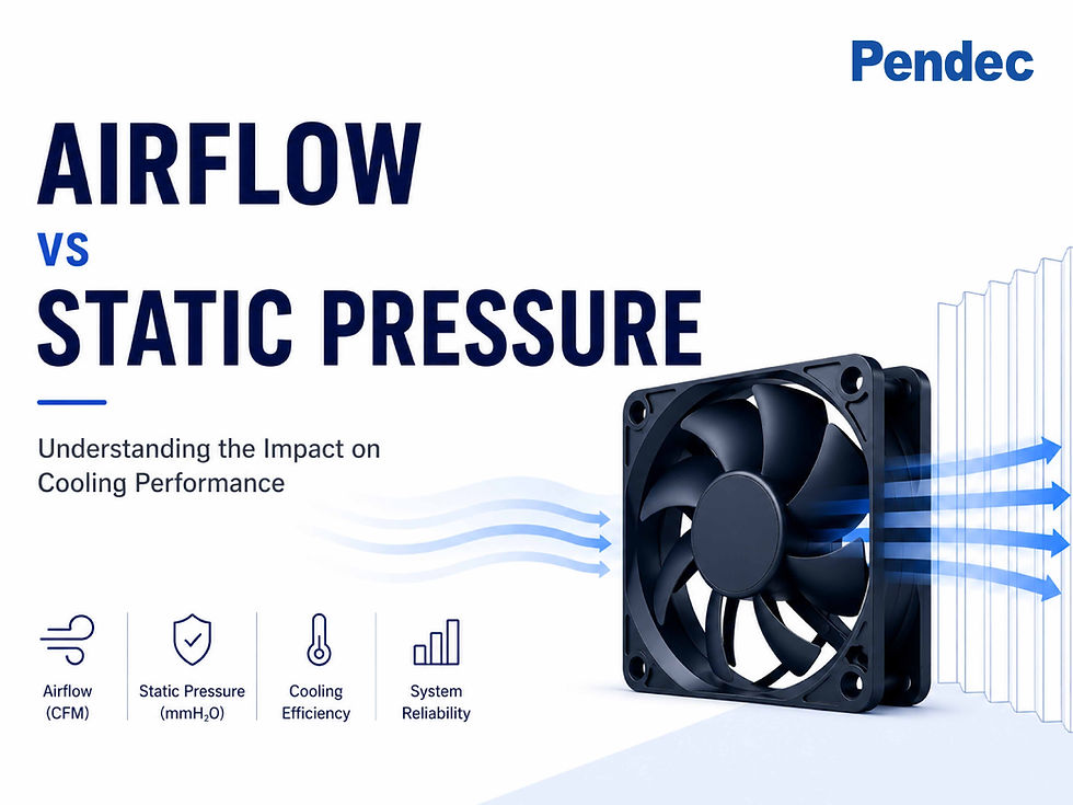
✔ Account for System Impedance: High-density fins and dust filters increase flow resistance. High-static-pressure fans may be required — airflow rating alone is insufficient for fan selection.
✔ Build In Thermal Margin: Add 10–30% thermal margin above calculated requirements to accommodate ambient temperature variation and component aging over time.
✔ Combine Simulation with Physical Testing: Use CFD (Computational Fluid Dynamics) simulation, thermal imaging analysis, and wind tunnel testing to validate cooling calculation results against real system behavior.

6. Conclusion
Accurate cooling calculation is the starting point for all effective thermal design. Virtually all electronic power consumption converts to heat; thermal resistance is the core parameter of thermal design; and fan selection cannot rely on airflow alone — system impedance and actual operating point must be evaluated together. High thermal density is the defining challenge of modern electronics, and rigorous cooling calculation is the foundation for building products that are both reliable and competitive.
📌Pendec provides professional wind tunnel equipment and thermal engineering specialists to help customers measure actual operating points and validate cooling calculation results after system integration. Our current product lineup includes DC axial fans 4028 (40×40×28mm) and 4056 (40×40×56mm), an intelligent cooling fan, and a waterproof fan module — all backed by an industry-leading 3-year warranty. Additional models are continuously expanding. Contact us for a customized thermal design recommendation.


Comments